The Project
The objective of this project was to develop a microcontroller-based device capable of rapid 3D spatial mapping. Using a Time-of-Flight (ToF) sensor attached to a stepper motor, the device achieves precise 360° spatial scanning and visualizes the captured data using Python libraries and PC connectivity.
My Role
This project was completed entirely independently. My responsibilities included programming the ARM architecture-based microcontroller, wiring and connecting the hardware, and conducting thorough testing.
Key Features
- Rapid 3D Spatial Mapping: Utilizes the VL53L1X ToF sensor for precise distance measurements up to 4 meters, with a high ranging frequency of up to 50Hz.
- Intuitive Operation: Features a simplified user interface with dedicated buttons for starting and resetting the scanner.
- Full 360° Scanning: Employs a 28BYJ-48 Stepper Motor with 2048-step precision, controlled in Full Step mode, for accurate positioning and smooth operation.
- Advanced Data Capture: Ensures efficient I²C communication for seamless data transfer and enhanced data capture.
- PC Connectivity: Establishes serial communication with a Python interface for easy data transfer and visualization.
- Microcontroller Efficiency: Powered by an MSP432E401Y microcontroller operating at 60MHz for optimized performance.
Programming the Microcontroller
The microcontroller and its functionality were programmed in C using the Keil software development environment, designed specifically for ARM Cortex-M based microcontroller devices. The program instructs the microcontroller to wait for a button input and then rotate the stepper motor 360°. Every 11.25°, the ToF sensor takes a scan.
int on = 0;
int CW = 1;
uint16_t z_coord = 0;
uint16_t z_interval = 100;
float degree = 0;

while(1) {
    int input = GPIO_PORTM_DATA_R &= 0xF;
    if((input) == 1){
      SysTick_Wait10ms(5);
      while((GPIO_PORTM_DATA_R &= 0xF) != 0){}
      if((input & 0b00000001)==1){
        if (on==0){ on = 1; } else { on = 0; }
      }
      SysTick_Wait10ms(5);
    }
    if ((on==1)){
      int rotation_Step = 512;
      GPIO_PORTF_DATA_R ^= 0b00010000;
      if (CW == 0){
        degree = 0;
        for (int i=0; i<=rotation_Step; i++){
          uint32_t delay = 1;
          if((i%(rotation_Step/32)) == 0){
            GPIO_PORTF_DATA_R ^= 0b00000001;
            status = VL53L1X_GetDistance(dev, &Distance);
            status = VL53L1X_ClearInterrupt(dev);
            sprintf(printf_buffer,"W,%u,%u,%f\r\n", Distance, z_coord, degree);
            UART_printf(printf_buffer);
            degree += 11.25;
          }
          GPIO_PORTH_DATA_R = 0b00000011;
          SysTick_Wait10ms(delay);
          GPIO_PORTH_DATA_R = 0b00000110;
          SysTick_Wait10ms(delay);
          GPIO_PORTH_DATA_R = 0b00001100;
          SysTick_Wait10ms(delay);
          GPIO_PORTH_DATA_R = 0b00001001;
          SysTick_Wait10ms(delay);
          if((i%(rotation_Step/32)) == 0) {
            GPIO_PORTF_DATA_R ^= 0b00000001;
          }
        }
        CW = 1;
      }
      // Counter-clockwise rotation follows same pattern...
      GPIO_PORTF_DATA_R ^= 0b00010000;
      on = 0;
      z_coord += z_interval;
    }
}
UART and Python Integration
Via UART communication, the PC can read the output from the microcontroller. A Python program then manipulates this data. The microcontroller sends each scan's data in the format [Distance, Z Coordinate, Degree].
import serial
import math
import numpy as np
import open3d as o3d

s = serial.Serial()
s.baudrate = 115200
s.port = 'COM3'
s.timeout = 10
s.open()

s.reset_output_buffer()
s.reset_input_buffer()

input("Press Enter to start communication...")
s.write(b's')

data = []
matchflag = True
setsOfScan = 3
w_count = 0

while (matchflag == True):
    x = s.readline()
    dec = x.decode()
    if (len(dec)>0):
        if (dec[0] == 'W'):
            data.append(dec)
            w_count += 1
    if (w_count == (setsOfScan*32)):
        matchflag = False

s.close()
The data is then converted to 3D coordinates and visualized using Open3D:
pcoords = []
for item in data:
    subitem = item.split("\r")
    coord = subitem[0].split(",")
    pcoords.append([int(coord[1]), int(coord[2]), float(coord[3])])

coords = []
for coord in pcoords:
    temp = [
        coord[0] * math.cos(math.radians(coord[2])),
        coord[0] * math.sin(math.radians(coord[2])),
        coord[1]
    ]
    coords.append(temp)

point_cloud_data = o3d.io.read_point_cloud(filename, format="xyz")
o3d.visualization.draw_geometries([point_cloud_data])
Hardware
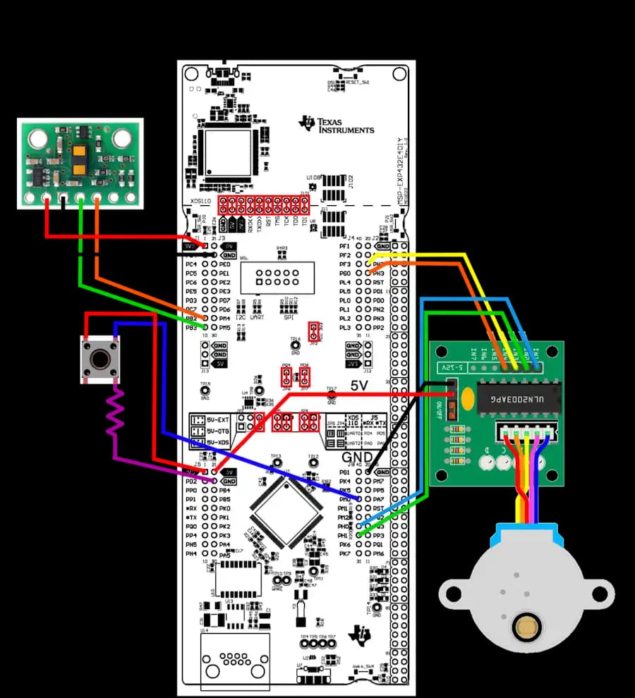
Constructing the device required a thorough understanding of the microcontroller. Below is the circuit schematic used in the project.
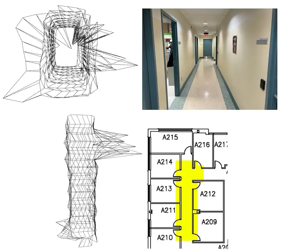
Final Product
Below are images comparing the line visualizations created using Open3D with photographs of the actual area.